Introduction - Build Skill Level: Advanced
Well it's time for me to enter the world of quadcopters. As a kid I've always been mesmerized by the RC aircraft community. Given my interest and knowledge with micro-controllers, in this case the Arduino Atmel based boards, I felt it was time to bring the two together and assemble my own quadcopter.
This is my very first build, and is by far not the easiest route to take in assembling your first quad. I chose to do it this way to learn and put my electronics skills to the test. Enjoy!
THE BUILD

Given that I am just fresh out of the research stage with the project, I have only just ordered the parts I feel will work well as an inexpensive but well performing quadcopter platform.
-Arduino Uno R3 (amazon.com) $25
- Standard Protoshield (Ebay) $10
- IMU Digital Combo Board - 6 Degrees of Freedom ITG3200/ADXL345 (Sparkfun) $65
-Logic Level Converter (Sparkfun) $2
- ST360 Quadcopter frame (Hobbyking) $17
- 4x ST2210 Brushless Motors (Hobbyking) $20 (usually $40, I got a good deal)
- 4x 8045 Propellers (Hobbyking) $4
- 4x Hobbyking 20A BlueSeries ESC's (Hobbyking) $40
- Turnigy 2200mAh 3s Lipo Battery (Hobbyking) $14
- Various hardware for mounting (Hobbyking) $5 - $15
- HXT900 Micro Servos + Fiberglass FPV Gyro Camera Mount (Hobbyking) $12
- HobbyKing 2.4Ghz 6Ch Tx & Rx (Basic 6 channel transmitter & reciever combo) 22.99
Total: ~$230
Much of the inspiration comes from a blogger named Russell who built a quadcopter UAV for his thesis research in the field of autonomous UAV's. Scout is the name, and it's primarily based off of the arduino platform running AeroQuad firmware/software. The stabilization systems of the quad will utilize the open source arduino platform to auto stabilize the aircraft, take inputs from a standard 2.4Ghz receiver, process the data, and control the motors using PWM pulses through the ESCs. The ultimate goal is to set this thing up for autonomous flight using air pressure sensors, GPS, magnetometers, and various other sensors to develop the aircraft into a robust autonomous aerial platform. Using the gyroscopic stabilization code I used for the motorcycle camera mount, the quadcopter will also be able to take and transmit stabilized video to the operator using video tx/rx. I will continue to update this page as my project proceeds, hopefully this blog will provide insightful information and reference material for those looking to enter the world of Arduino (atmega) based quadcopters. Parts are expected to arrive within a couple weeks (darn Hobbyking and their Chinese warehouse). Stay tuned.
Stabilization System
Received the sensors today that were shipped from Sparkfun and Sainsmart. The sensors include the 6 Degrees of Freedom ITG3200/ADXL345 (accelerometer and gyroscope) & logic level converter from Sparkfun as well as a BMP085 (barometer) from Sainsmart. The ITG3200/ADXL345 is the meat and potatos of the system, this chip alone will be the primary sensor utilized to keep the machine stable in flight. I won't cover much regarding the BMP085 at this point because I have found the Aeroquad code compiles too large for the 32k of flash memory on the Uno board with the altitude hold algorithms active. I will probably implement the sensor later when I decide to switch to an Arduino Mega for the extra memory.

Basically all that is needed to be done is wiring up the ITG3200/ADXL345 to the arduinos I2C lines utilizing the logic level converter to ensure the 3.3V signals from the IMU are properly read by the arduino's 5V inputs. The wiring diagram below is a good illustration of exactly how the flight control system is to be assembled. Once wired up, the latest flight control code and software should be downloaded from the Aeroquad website and compiled/uploaded to the Uno Board. In order for the code to function properly it is important to thoroughly read over the UserConfiguration.h library and ensure that you uncomment the proper #define statements for whatever configuration you're using. It is pretty self explanatory, they do a very good job explaining right in the code exactly what all the user configurations do/control. It's also important to note that at the time of me writing this, the current code is v3.0.1
 |
| source |

Once everything is plugged in and ready for testing, it's time to install the Aeroquad Configurator Software also available on their website. At the time of me writing this the software is v3.2. Once you boot it up it is important to select the proper baud rate (115200) and com port for proper serial communication with the board. Click connect, and the board should connect up and display what sensors were recognized. Going into 3D view graces the user with a beautiful 3D representation of the quadcopter and its projected orientation based off of the sensor readings. More information regarding the software will be provided as it comes time for sensor calibration, PID tuning, and receiver setup. In the meantime, enjoy this little vid of my first time plugging it all in.

Build Process
Received the parts a couple of days ago and since then have assembled the quad in what little time I had away from work. I'm going to run through the physical build process in this post and give a detailed rundown of every part that was used. The next post will go into detail about the firmware, code, PID tuning, and the Aeroquad Configurator software.
Power Harness
You could always buy a power distribution board from hobbyking but since this build was going to be DIY with everything but the firmware I wired up my own using 12 gauge stranded wire. It is absolutely necessary to use the proper gauge of wire based on the amount of voltage through the circuit. 12 gauge is good up to 20 amps so we wont have any problems there.

The harness just needs to be wired in parallel with the battery, I also added a separate 2.2mm power jack to separately power my microcontroller. I made that choice because its nice to be able to power cycle the flight board without pulling the battery cable. All of the connectors I use in this build are XT60 connectors.
Stabilization System
Used an Arduino Uno microcontroller with a standard prototyping shield. While a breadboard is certainly not a platform for final electronics circuitry, this being the first time building and flying a quadcopter I wanted things to be as simple as possible to troubleshoot and pull apart. The breadboard looks so cool and works so well I may just keep it how it is :) See previous posts for that actual wiring schematic for the sensors onto the micrcontroller. The schematic is applicable only too the wiring of the 6DOF IMU and the logic level converter, the motor and receiver connections are NOT accurate!

Electronic Speed Controllers (ESC)
Electronic speed controllers are the nifty little devices that take pulse width signals from micrcontrollers and use that signal in order to quickly change the rotational velocity of the motor. It's two main power terminals need to be hooked up to the 4 connections of the wiring harness (seen above) , the signal wire plugs into a pin on the arduino that is applicable to the version of firmware your using, and make sure that there is a ground wire connected to ground to ensure a reference for the signal wire. The three wires going to the motors need to have bullet connectors soldered on so the polarity of the motors can be easily changed in case they are not spinning the desired direction when you go to spin up the quad for the first time. So basically, power connection needs an XT60 connector, the three motor wires need bullet connectors, and the signal ribbon will need the signal wire and a ground connection plugged into the microcontroller.

Remember the ESC's need to be rated for the max current draw of the motors at full throttle. Just check out the spec sheets of your motors as a reference for this information.
Another interesting tidbit of info here as well; most ESC's are designed for less intense and maticulous motor control. Meaning, their "report rate" or "refresh rate" isn't quite as fast as it could be. What this means is the ESC's have the ability to be reprogrammed or flashed with third party firmware to set a higher refresh rate. This allows the motors to respond to the microcontroller's commands faster resulting in smoother flight. The most popular third party firmware in the quadcopter community right now is without a doubt the SimonK firmware. I will have a post in the future describing how to use the hobbyking flashing tool to flash these blue series esc's to the SimonK firmware.
Frame
The frame plays a big part in how the quadcopter will be ultimately layed out and designed. This build is utilizing a 360mm wide frame which is quite small. I do not know how the flying characteristics change from the size of the frame because I simply have never done this before, search forums to the answer to that question. Make sure the frame your using has clearance for your battery and electronics, in my case the frame was designed for nothing to fit under it apparently, so I rigged up some leg extensions using some PVC pipe. Turned out quite nicely if I do say so myself, it also adds a layer of protection for my frame to keep it from taking hard impacts directly.


Batteries
The absolute best option currently in terms of battery technology for this kind of application are lithium polymer batteries. These batteries come in all kinds of varieties ranging from single cell up to 10+ cells. Each cell has a voltage of roughly 4.2 volts and in the case of a quadcopter, a good voltage range with enough mAh to fly for a reasonable amount of time ranges from about 2000-5000mAh and 3 cells for a total voltage of about 11.1 - 12 volts. The Arduino has an onboard voltage regulator rated to 16 volts so the flight board can be easily powered straight from the main lipo power harness. The alternative would be to power the Arduino through the ESC's, but it's really up to the assembler. What's so special about lipos are their ability to draw massive amounts of current at one time, although, each lipo has different capabilities. The amount of current the lipo can output is derived from its "C" rating and its capacity. For instance, a lipo with 2200mAh and is rated for 40C can pull a max current of 2.2A x 40C = 88 Amps!! That's a massive amount of current at one time! In the case of my quad, each of my ESC's are rated for 20amps max, so I could theoretically pull 80 amps of current through the quad at any given time; but due to good design decisions, I will never reach that limit. It is a good idea to "overdesign" the quad by a margin to ensure all the electronics are operating at a moderate level, this will greatly improve the longevity of the hardware.

Props
There are all kinds of different prop variations to choose from. Props are advertised by their length and pitch. Depending on the size of the copter and the power of the motors you're going to want to choose what's best for your configuration. In my case, I have a 360mm wide frame, and the props I use are 8045's meaning 8" x 4.5". That is 8' long, 4.5" pitch. For my setup it is perfect for gentle maneuvering, fast acceleration, and has plenty of overall speed. Do a little research on what people are using with their particular motors and frames, there isn't any hard and fast rule on this so I'll leave it up to you. Make sure that when purchasing the props that two of them are CW (clockwise) and the other two are CCW (counterclockwise). This is important because otherwise the quad's yaw would get all out of wack in flight. It relies on counter rotating propellers to ensure the quad doesn't rotate out of control!
Receiver
Any 2.4Ghz receiver and transmitter can be interfaced with the arduino and the Aeroquad firmware. The userconfiguration.h library has several different transmitter types, several PPM varieties as well as standard PWM. In my case I have the cheapest 6CH transmitter and receiver you can buy from hobbyking and it is working great! You want at least 6 channels for all your flight controls and 2 for mode switching.

Each signal wire corresponds to a different digital pin on the arduino board. In the case of this firmware version they are digital pins 1, 3, 4, 5, 6, & 7. Each one will correspond with a different switch on the transmitter. Just load up the transmitter calibration page on the aeroquad software and start moving the flight sticks around. You'll figure it out. The reciver's battery connection can simply be plugged into the arduino's 5V line and grounded.
Charger
To charge the lipo batteries I am using a Turnigy Accucel 6, it can charge at up to 6 amps per hour. Of course you need a power supply that can handle that kind of amperage, but I'm using a simple 4 amp power supply from hobbyking that does just fine for my needs. There is some very important information that one needs to understand about charging lipo batteries so pay attention!

there are different charge rates that are measured in an arbitrary value known as C's. All modern Lipos are at least happy at a charge rate of 1C and most will charge at 2C. Never charge faster than the recommended rate from the manufacturer. Now, how does the C value relate to how many amps? Well, if you have a 2200mAh battery then 1C charge rate will be 2.2Amps. (milli = 10^-3). So following this pattern 2C charge rate for this battery would be 4.4 amps. When I charge my 2200 - 3000mAh lipos I just set it at a 4amp charge rate and call it a day. It will charge a 2700mAh battery from 10V to 12.6V in about 45 minutes at this rate! Remember when flying your quadcopter to quite flying when the battery voltage hits just below 10 volts (3.3V per cell) because lipos can be damaged if discharged to far below that voltage ceiling. If your charger has a storage mode option make sure and use that when you dont plan to use your batteries for more than a couple days, this will ensure a longer lifespan and prevent degrading. You never want to leave a fully discharged or fully charged lipo sitting around for too long.
Latest changes
I went ahead and swapped out the entire Arduino UNO bard and installed a mega with a protoboard for the sake of plug and play. What's great about the Arduino Mega is the increased memory so it can fit the software needed for extra sensors like a barometer and gps. I have added a BMP085 barometer to the mix and am in the middle of testing the altitude hold feature built into Aeroquad. The quad is really dialed in now and I have loads of information about PID tuning I will get to in later posts. But for now all I have to say is WOW this thing is flying amazingly! So smooth and precision once the PID's are dialed in.
Tonight I finally received my USBasp firmware flash tool along with the genious Hobbyking adapter to flash Atmel based ESC's. Loaded up the KK flashing tool software and flashed the SimonK firmware onto my ESC's. I will also add more information about the flashing process, its benefits, and the PID tuning after the flash. For now, check out the pictures of the latest layout!


I will be adding some really cool FPV and general quadcopter videos in the future so stay tuned for that. My work schedule makes sure I don't have any daylight to fly in during the week. :)
Software
Since this is a quadrotor aircraft their simply has to be a computer controlling the speed of the rotors in order to ensure a stable flight. The computer this quad is using is the atmega328 running off an Arduino Mega platform. The software that is loaded onto the microcontroller (computer) was designed by an open source community known as Aeroquad. Open source meaning the code is free to use and manipulate how you please. Being compatible right out of the box with the Arduino platform I would like to say it was a breeze to get up and running, but it was and it wasn't. It certainly helps to have a good understanding of basic C programming in order to troubleshoot things along the way. The parts I put together weren't exactly supported as a predefined set of hardware that would have made it plug and play. But it only came down to changing a couple lines of code so it was ultimately no big deal. I originally started this project utilizing an Arduino Uno but have since moved and designed a new layout for the Arduino Mega for the sake of the added memory and space for more onboard sensor packages.
The Aeroquad software can be downloaded here. You will need the configurator and the Aeroquad Vx.x software. Make sure the Arduino drivers are installed on the computer as well, not going to get into how to install unsigned drivers, I'm sure you can figure it out. Open the software in the IDE of your choice, for the sake of simplicity I will do it in the standard Arduino IDE. The settings for the software are in the userconfigurations.h library, opening this library we are graced with a plethora of configurations most of which are well explained in the code itself.

The configurations are set by uncommenting the #define statements that pertain to your configuration. In my case AeroQuadMega_v21 will work just fine from a hardware standpoint, quadXConfig to make it a quadcopter in the X configuration, USE_400HZ_ESC we will go over later as it has to do with the ESC firmware flashing process, for now leave that undefined. I'm not going to go over all the configurations as they are all self explanatory but there was at least one thing that I had to change to get the Arduino Uno to work properly with just a standard PWM transmitter.
//#define NormalReceiver // This does nothing really, but it indicates users that they don't have to define other options here if they have a normal receiver
//#define RemotePCReceiver // EXPERIMENTAL Use PC as transmitter via serial communicator with XBEE
//#define ReceiverSBUS // Use a Futaba sBUS RX, connect sBUS data line via an inverter (see wiki) to Serial2 RX, supports up to 8 channels on v2 and STM32 boards
//#define ReceiverPPM // Use a PPM receiver
//#define ReceiverHWPPM // Use a PPM receiver with HW timer (less jitter on channel values than PPM), needs a HW modification (see wiki)
#define RECEIVER_328P
// You need to select one of these channel order definitions for PPM receiver
//#define SKETCH_SERIAL_SUM_PPM SERIAL_SUM_PPM_1 //For Graupner/Spektrum (DEFAULT)
//#define SKETCH_SERIAL_SUM_PPM SERIAL_SUM_PPM_2 //For Robe/Hitec/Futaba/Turnigy9X+Er9X
//#define SKETCH_SERIAL_SUM_PPM SERIAL_SUM_PPM_3 //For some Hitec/Sanwa/Others
in version 3.x of this code with an Arduino Uno defined as the board to upload to in the IDE it will not compile with NormalReceiver defined, I had to manually define the RECEIVER_328P library due to a bug in the code. Because there are so many hardware configurations that can be put together there are obviously going to be bugs in the nest of define statements throughout the Aeroquad code. I give special thanks to my buddy Dale for helping me with that issue! When you compile the software with the Arduino Mega board it does not throw that compiling error so you should be good to go.
Once the board has the code uploaded its time to load up the amazing Aeroquad Configurator software. This software package has a nice easy to use interface to calibrate, tune, and stream realtime data from the quadcopter's sensors. With Xbee's this data can be streamed wireless to a computer in realtime!

Here is the main screen you get when you first launch the software. First thing to do is get the board connected with the software. Bottom right you want the baudrate set to 115200, select the proper com port for the board, and hit connect. It will come up with the window in the bottom right that the board has been detected and what sensors it detects as well. The first thing to do once connected is to initialize the EEPROM using the "initialize EEPROM" button. EEPROM is the long term memory location on the microcontroller that will store the tuning information that will be crucial for getting the Quadcopter flying smoothly with precision. Next, put the quadcopter on a flat surface and calibrate the gyro and run through the accelerometer calibration process. At the top there is a drop-down menu that will give access to loads more features as seen below.
Vehicle Status

Vehicle Attitude

Motor Commands
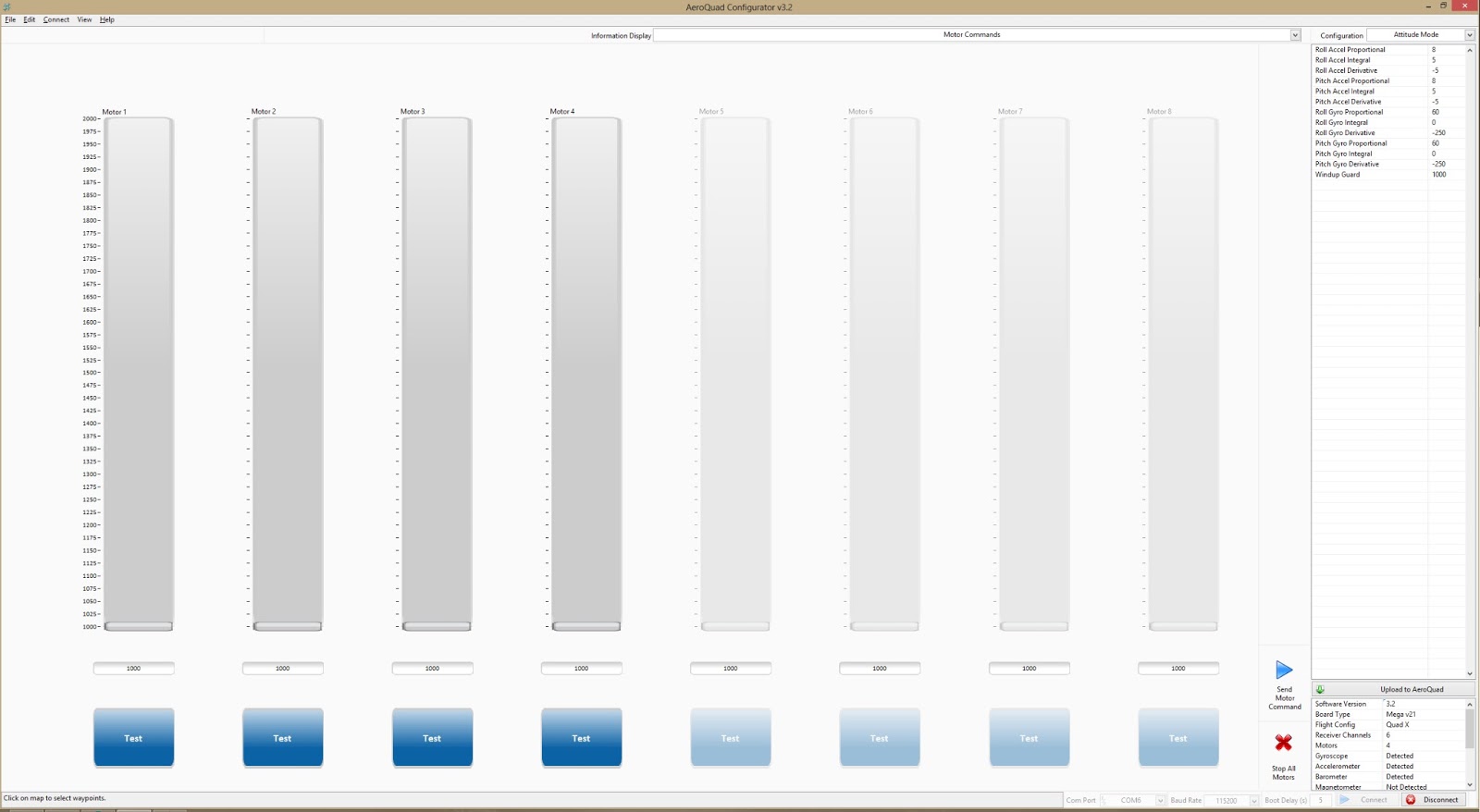
Sensor Data
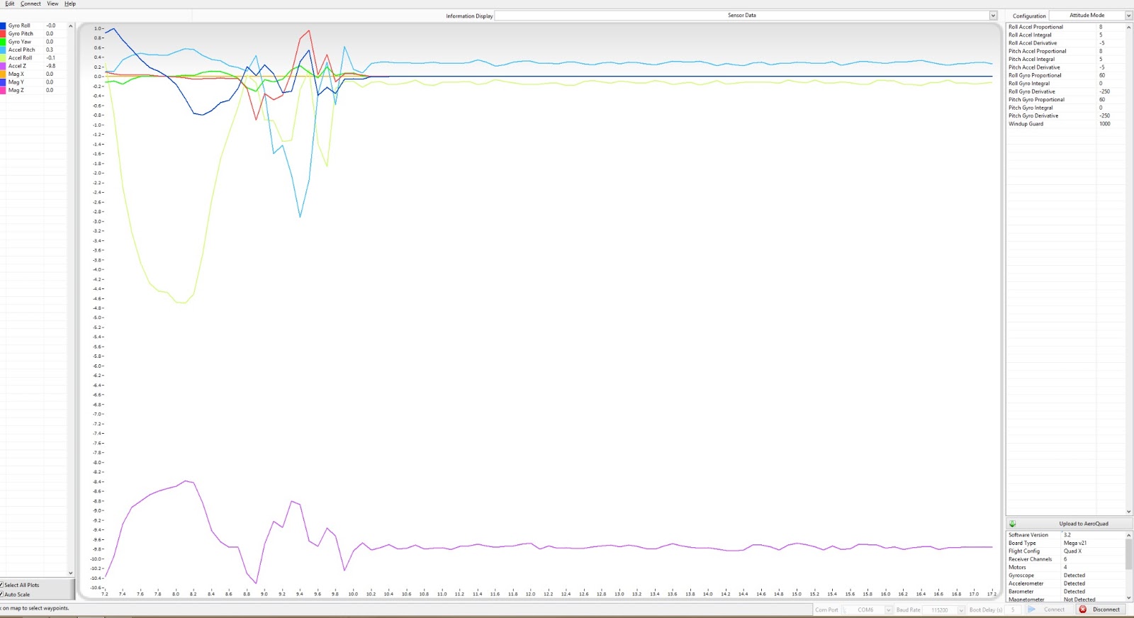
There are loads more features including a route mapper using google maps for setting up GPS guided autonomous flights! As you can see in the top right of the interface there is a box of values where you can adjust the PID setting of the vehicle as well as loads of other important things such as transmitter settings, sensor calibrations, and even camera stabilization. This is a very impressive piece of software with loads of configurations and its only growing as the community adds to it!
Saw your post on the aeroquad forums. Keeping an eye on your blog bro. Interested in a cheap quadcopter build for some experimentation of my own and like what you have done. Thanks for sharing!
ReplyDeleteIm relatively new to the QuadCopter scene, and Im not particularly interested in RC quads, I'm really interested in programmed Quad flight. After the completed build, how am I able to start programming its flight, specifically just like your blog says, using the onboard sensors make it autonomous and programming flight in 3 dimensions. Is it plug and play into computer USB with software?
ReplyDeleteThis comment has been removed by the author.
Deletei sent an email did you receive it ?!
ReplyDeleteHi, your build inspired me a lot for my quad. I am using Aeroquad with Arduino UNO and MPU9150
ReplyDeleteI managed to get the sensors to work. However I am wondering how to get the receiver to work as I saw the pin allocation and tried to reproduce it.
Receiver
Throttle : Digital 4
Ailleron : Digital 2
Elevator : Digital 5
Rudder : Digital 6
Gear : Digital 7
AUX1 : Digital 8
Motors :
Front : Digital 3
Rear : Digital 9
Right : Digital 10
Left : Digital 11
Is it the right connexion ? where should the receiver main signal wire go in the Arduino ?
Did I select the wrong option in the UserConfig.h ?
I uncommented #define NormalReceiver and #define ReceiverPPM I am using a Spektrum AR6115E
Your help would be much appreciated ... Thanks !
thank you for share I really want to learn Arduino and this project is very exited
ReplyDeleteHi, I really like your post. I also want to build my own quadcopter based on Arduino, but I'm using Arduino Yun.
ReplyDeleteFor the parts, mostly I use the same with you: the frame, ESC, battery. Only the controller is different.
I want to ask some questions:
1. How much is the total weight of your quadcopter?
2. Do you think I can use Aeroquad on Yun?
Thanks before!
I must say that the freshness of your blog has surely left me mesmerized, there were no better words to express and I will surely be a regular visitor to your blog.
ReplyDeleteQuadcopter in India